Power supply is rarely the spec buyers ask about first. But it is often the one that determines whether a bulk order comes back clean or comes back with a stack of warranty claims. A head unit that reboots randomly, drains a customer’s battery over a weekend, or misbehaves the moment the alternator kicks in usually is not a software problem. It is a power supply mismatch that should have been caught during sourcing.
This guide covers what car stereo power supply actually involves. It also covers what to verify before committing to a supplier. For a full view of all hardware decisions, see our car stereo hardware components overview.
Car Stereo Power Supply – Definition and Automotive Context
What Is a Car Stereo Power Supply?
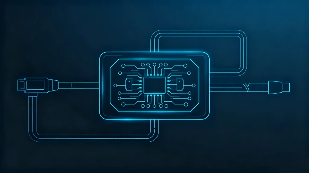
A car stereo power supply is the electrical system that provides the voltage and current a head unit needs to operate. It covers power input, internal voltage regulation, and distribution to the unit’s components.
Vehicle Electrical Systems
Vehicle electrical systems run on a nominal 12V DC. But that number is closer to a baseline than a guarantee. The actual voltage fluctuates constantly. The system carries electrical noise and occasional spikes. A well-designed power supply needs to absorb these without issue.
Why This Matters in B2B Sourcing
This matters more in B2B sourcing than it might first appear. An incompatible or poorly regulated power supply can lead to unit failure. It can cause unexpected reboots. It can cause steady battery drain that a customer only notices days later. Weak voltage regulation shows up as audio noise, display flicker, or general instability under load. On the standby side, excessive current draw while the vehicle is parked can quietly drain a battery over days or weeks. This is a problem that generates support calls long after the unit shipped.
Typical Automotive Vehicle Voltage and 12V Power-Supply Foundation
Not a Steady 12V Line
Before evaluating a head unit’s power specifications, it helps to understand what the vehicle side of that connection actually looks like. It is far from a steady 12V line.
Engine Off
With the engine off, voltage sits close to battery voltage. This is typically around 12V.
Engine Running
Once the engine starts and the alternator takes over, voltage climbs to roughly 13.8V to 14.5V. This is the range a head unit spends most of its operating life in.
Dips and Spikes
The dips and spikes are where things get more demanding. Cranking the starter motor can pull voltage down to 10V or lower for a brief moment. Everyday load changes — headlights switching on, air conditioning kicking in, heated seats activating — cause smaller but constant voltage variation throughout a drive. On top of that, the alternator itself generates electrical noise. Sensitive electronics need to filter this out rather than pass it through to the display or audio output.
Normal Operating Environment
None of this is unusual or a sign of a faulty vehicle. It is simply the normal operating environment automotive electronics are built to handle. The practical takeaway for buyers is that a head unit rated only for a narrow, stable voltage window is poorly matched to how vehicle electrical systems actually behave. For step-by-step installation guidance, see our head unit installation guide.
Core Car Stereo and Head-Unit Power Requirements
Two Different Operating States
Head unit power requirements break down into two very different operating states. Both need to be checked independently.
Normal Operation
During normal operation, nominal voltage sits at 12V DC. Most units specify a wider operating range — commonly 10V to 16V — to accommodate the fluctuations described above. Operating current varies by feature set and usage. It typically falls somewhere in the 3A to 10A range. This depends on display brightness, audio output level, and how many peripherals are active at once. Multiplying voltage by current gives the power consumption figure, measured in watts.
Standby Power
Standby power tells a different story. Once the ignition is off, the unit still needs a small trickle of current to retain settings, clock time, and memory. A well-designed unit keeps this standby draw in the range of roughly 1mA to 10mA. Anything meaningfully higher starts to matter for a parked vehicle’s battery health over time.
Protection Circuits
Fuses and voltage regulation circuitry sit behind both of these figures. They protect the unit and the surrounding wiring from surges or faults.
What to Look For
Buyers evaluating a spec sheet should treat operating current and standby current as two separate line items. They should not be a single “power requirement” figure. They affect completely different aspects of real-world reliability.
Head-Unit Power Input and Basic Wiring Fundamentals
Three Distinct Connections
Power reaches a head unit through three distinct connections. Understanding their separate roles avoids confusion during sourcing conversations.
Battery Line (B+ or Constant 12V)
The battery line supplies continuous power directly from the vehicle battery. It keeps memory, clock, and saved settings intact even when the vehicle is off.
Ignition Line (ACC or Ignition)
The ignition line is switched power that turns on and off with the ignition key. It powers the unit’s active functions only while the vehicle is running or in accessory mode.
Ground (GND)
Ground completes the circuit through a chassis connection.
Beyond the Core Connections
Beyond these three core connections, wire gauge needs to match expected current draw to avoid voltage drop or overheating. An inline fuse needs to be sized correctly to protect both the unit and the vehicle’s wiring. Connection quality — secure, corrosion-free contacts — prevents intermittent power issues that are notoriously hard to diagnose after installation.
Wiring Harnesses
Wiring harnesses simplify this considerably. Vehicle-specific harnesses handle the connector matching automatically. Universal harnesses require more manual wiring work and closer attention to these fundamentals.
Car-Stereo Power Consumption and Current-Draw Requirements
Two Different Figures
Operating current and standby current serve entirely different purposes in a spec review. Conflating them is a common sourcing mistake.
Operating Current
Operating current reflects what the unit draws while it is actually running. This is generally in the 3A to 10A range depending on active features. Peak draw occurs when an internal amplifier is pushing speakers at higher volume. This figure determines whether the vehicle’s wiring gauge and alternator capacity are adequate for the installation.
Standby Current
Standby current, sometimes called quiescent current, is what the unit draws while parked with the ignition off. Good units generally sit in the 1mA to 10mA range. Anything consistently above that starts posing a real risk of battery drain over days or weeks of inactivity. This is particularly true for vehicles that sit unused for extended periods.
The Practical Distinction
The practical distinction matters for different reasons. High operating current is primarily a wiring and alternator-capacity concern. High standby current is a battery-health concern. It can leave a customer with a vehicle that will not start after a few days parked. Buyers sourcing at volume should request both figures explicitly. Do not assume a low operating-current spec implies a correspondingly low standby draw.
Vehicle-Side Electrical Compatibility Factors for Car-Stereo Power Supply
Beyond the Head Unit’s Specs
Beyond the head unit’s own specifications, several vehicle-side factors determine whether a given power supply setup will actually work reliably once installed.
Electrical System Type
Electrical system type is the most fundamental check. Standard passenger vehicles run 12V systems. Commercial vehicles and trucks often use 24V systems. These require a head unit specifically designed for that voltage range.
Load Conditions
Load conditions matter too. Alternator output needs to be sufficient for the added draw. An aging or marginal battery can introduce voltage instability that a healthy battery would not.
Battery Sleep Behavior
Some modern vehicles also implement battery sleep behavior. Accessory power gets restricted after a period of inactivity to conserve battery charge. This sometimes requires a CAN Bus wake-up signal to restore accessory power correctly.
Ongoing Voltage Fluctuations
The same voltage fluctuations covered earlier — cranking dips, load-switching spikes — remain relevant here as ongoing conditions. The installed system has to tolerate them throughout its service life. This is not just during initial power-on testing.
B2B Sourcing Considerations for Car-Stereo Power-Supply Specifications
Sourcing Checklist
Turning these technical points into an actionable sourcing checklist.
- Operating voltage range — verify coverage of at least 10V–16V, wider for 24V-system applications
- Operating current — confirm typical and maximum current draw figures
- Standby current — verify quiescent current, ideally under 5–10mA to limit battery drain risk
- Power input pins — confirm battery, ignition, and ground wiring are clearly specified
- Fuse rating — verify appropriate fuse sizing is documented for the unit
- Voltage tolerance — confirm the unit is rated to handle typical vehicle voltage fluctuations
- Documentation — request full electrical specifications rather than a single nominal voltage figure
- Sample testing — test power consumption, standby current, and voltage tolerance directly on samples before committing to volume
FAQ
Why do some 12V-rated head units drain vehicle battery when the vehicle ignition is switched off?
This typically comes down to standby (quiescent) current that is higher than it should be. The unit keeps drawing more power than necessary to maintain memory and clock functions even with the ignition off. Poor power circuit design, components that do not fully power down, or software that keeps background processes running longer than needed can all contribute. Buyers concerned about this should request the specific standby current figure. Do not assume any 12V-rated unit behaves the same way when parked.
Can a car stereo rated for 12V nominal input tolerate temporary vehicle-system voltage spikes?
A well-designed unit should. Automotive-grade power supply circuits are built with voltage regulation and protection components. These are specifically to absorb the spikes and dips that occur during normal vehicle operation, such as starter motor cranking or load switching. That said, “12V nominal” alone does not confirm how wide a tolerance range the unit actually supports. Buyers should look for a stated operating voltage range, such as 10V to 16V. Do not assume tolerance from the nominal figure alone.
What is the practical difference between operating current and standby current for B2B bulk retrofit projects?
Operating current is what the unit draws while actively running. It directly affects whether existing vehicle wiring and alternator capacity can support it without strain. Standby current is what the unit draws while parked with the ignition off. It directly affects whether a customer’s battery stays healthy over days of inactivity. For bulk retrofit projects across many vehicles, standby current tends to generate more after-sales complaints than operating current. Battery drain issues surface well after installation. They are harder to trace back to the head unit.
Why can two head units with identical nominal voltage specs exhibit different real-world power supply stability in the same vehicle?
Nominal voltage is just a starting point. Actual stability depends on the quality of the internal voltage regulation circuitry. It depends on how well the power supply filters alternator noise. It depends on how the unit responds to voltage dips during cranking. Two units can both list “12V DC” on their spec sheet. One handles a cranking voltage drop cleanly. The other reboots or glitches. This is exactly the kind of difference that a datasheet comparison will not reveal. Real-vehicle sample testing will.
What sample-test procedures can wholesalers run to validate head-unit power-supply behaviour before mass order?
A reasonable protocol includes measuring actual operating current under typical and maximum load. It includes measuring standby current with the ignition off over an extended period. It includes testing behavior during simulated voltage drops similar to starter cranking. Running samples through a burn-in period — continuous power-on operation over an extended stretch — helps surface early hardware instability. A short bench test would miss this. Requesting the supplier’s own burn-in and voltage-testing data as a starting point is useful. Then verifying key figures independently gives a more complete picture. Do not rely on datasheet claims alone.
Conclusion
Power supply mismatches are one of the more expensive mistakes to discover after a bulk shipment has already reached customers.