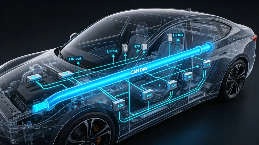
CAN Bus is a multi-master communication protocol widely used for communication between electronic control units (ECUs) in vehicles.
This guide focuses on how the CAN Bus protocol and network operate, including shared bus architecture, CAN nodes, message arbitration, message filtering, CAN frames, wiring, termination, and network topology.
If you are new to CAN Bus and want to understand its basic definition, role in vehicle electronics, aftermarket head units, and CAN Bus decoders first, see our What Is CAN Bus? B2B Guide to Vehicle Communication.
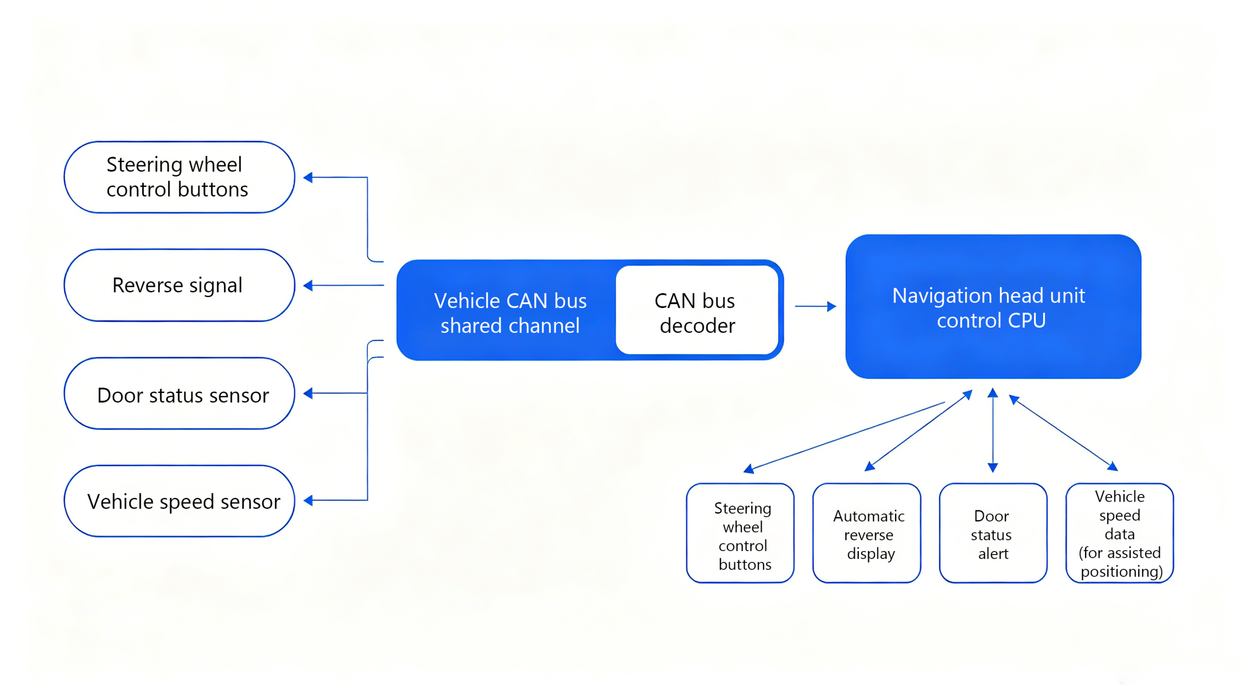
CAN Bus Working Principle: Shared Bus and Arbitration
CAN Bus Working Principle: Shared Bus and Arbitration
Every ECU on a CAN Bus network connects to a shared communication bus using CAN_H and CAN_L. Any connected node can transmit and receive CAN messages.
When multiple nodes attempt to transmit at the same time, CAN uses non-destructive bitwise arbitration to determine which message continues. The message with the highest priority, represented by the lowest numerical identifier, wins arbitration and continues transmitting without destroying the winning message.
The other transmitting nodes stop and wait until the bus becomes available again. This arbitration mechanism allows multiple ECUs to share the same communication bus while giving higher-priority messages access to the network first.
Message Filtering
Every ECU on the network receives every message, but each processes only the ones relevant to it based on the identifier.
Broadcast Protocol
CAN is fundamentally a broadcast protocol. Filtering happens at the receiving node itself, in hardware or software, not at the network level.
What Is a CAN Bus Message and Frame?
A CAN message contains information that is transmitted from one node to other nodes on the network. The message identifier helps determine its priority and allows receiving nodes to determine whether the message is relevant to them.
A CAN frame is the structured format used to transmit a message across the CAN network. A standard CAN frame contains fields including the start of frame, identifier, control information, data, cyclic redundancy check (CRC), acknowledgment (ACK), and end of frame.
The exact frame format depends on the CAN specification being used, but the basic purpose is the same: to provide a structured way for nodes to exchange data over the shared bus.
CAN Bus Wiring: Twisted Pair, Differential Signaling, Termination
CAN_H and CAN_L
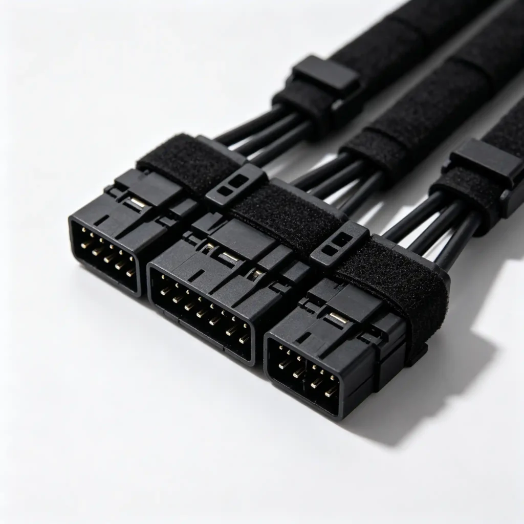
CAN Bus runs on a twisted pair of wires, commonly part of a car stereo wiring harness. The twist reduces electromagnetic interference.
Differential Signaling
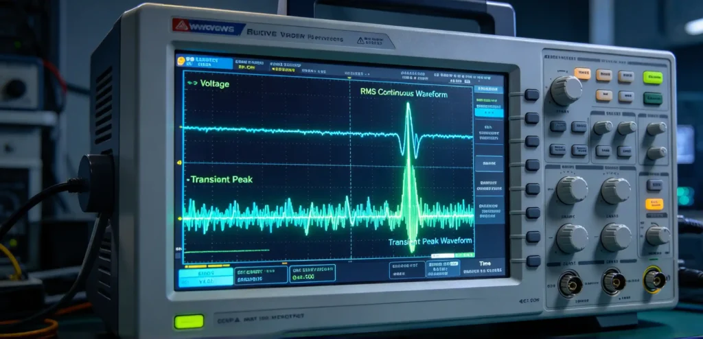
The voltage difference between CAN_H and CAN_L represents the data. Common-mode noise gets rejected.
Termination Resistors
Termination resistors are required at the ends of the bus to prevent signal reflections. Without proper termination, communication becomes unreliable or fails outright.
Topology Rules
Every node connects to the main bus through short stubs. The bus needs to run as a single line rather than a star pattern.
Common CAN Bus Wiring Errors
Common errors include wrong polarity, missing termination, and incorrect stub connections. These cause communication failures ranging from intermittent glitches to a complete loss of vehicle data functions.
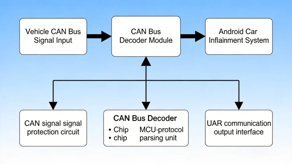
Why CAN Bus Decoders Must Be Vehicle-Specific
Different vehicle manufacturers and vehicle platforms may use different CAN message identifiers, data structures, and signal mappings.
As a result, a CAN Bus decoder designed for one vehicle platform may not correctly interpret messages from another vehicle without appropriate development and validation.
This does not mean that CAN Bus itself is a different communication standard for every vehicle. Rather, the communication framework is standardized while the actual messages and signals used by a particular vehicle system can vary.
This distinction is important when integrating aftermarket infotainment systems because the decoder must correctly interpret the messages used by the target vehicle.
For the B2B perspective on CAN Bus decoder compatibility, vehicle coverage, testing, and supplier evaluation, see our What Is CAN Bus? B2B Guide to Vehicle Communication.
FAQ
How does CAN Bus arbitration work?
When multiple nodes transmit at the same time, the message with the lowest numeric identifier wins arbitration and transmits first. Lower-priority messages wait.
What is inside a CAN frame?
A standard CAN frame includes a start of frame, identifier, control fields, data bytes, CRC, and acknowledgment.
Why do CAN Bus wires need termination resistors?
Termination resistors prevent signal reflections. The exact configuration depends on the specific vehicle network design.
Why can one decoder work on one vehicle but not another?
Because manufacturers implement their own message formats and data structures. A decoder needs brand- and often model-specific development rather than one universal solution.
Conclusion
Understanding CAN Bus at the protocol level helps explain how electronic control units exchange information across a shared vehicle network.
CAN nodes, message identifiers, arbitration, CAN frames, CAN_H and CAN_L, differential signaling, termination, and network topology all contribute to reliable CAN Bus communication.
For aftermarket infotainment integration, these technical concepts also explain why vehicle communication cannot always be treated as a universal plug-and-play system. The actual messages and signal mappings used by a vehicle may require platform-specific interpretation.
For the broader B2B perspective—including CAN Bus applications in aftermarket head units, decoder functions, vehicle compatibility, testing, and supplier evaluation—see our What Is CAN Bus? B2B Guide to Vehicle Communication.