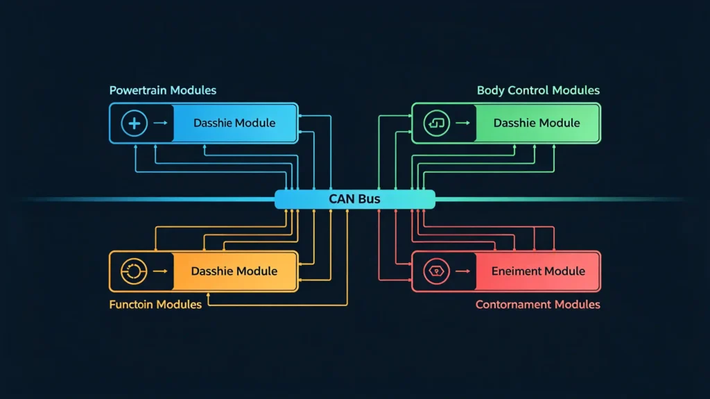
Every conversation about aftermarket compatibility eventually runs into the same three letters: CAN Bus. Most buyers know it matters without knowing exactly why. That gap is where sourcing mistakes happen. A decoder gets ordered. It does not work with the target vehicle. Nobody is quite sure whether it was the wiring, the protocol, or something else entirely.
This guide builds the foundational understanding. It covers what CAN Bus actually is. It explains how it works. It details what it controls across a vehicle. It covers its physical wiring. It provides the basic vocabulary around nodes and messages. It also explains why any of this matters when you are placing a bulk order. For a practical guide on steering wheel controls, see our steering wheel control integration guide.
What Is CAN Bus? Core Definition & Origin
Definition
CAN Bus, short for Controller Area Network, is a robust, multi-master serial communication protocol. Bosch originally developed it in the 1980s for automotive use. It lets microcontrollers and electronic control units (ECUs) talk to each other directly. This happens without a central host computer managing the conversation. For a complete guide on how CANBUS disruptions during ADAS calibration can affect navigation, see our ADAS calibration and car navigation guide.
Why CAN Bus Was Created
It exists because vehicles needed something better than a heavy, complex wiring harness. The old approach connected every component point to point. CAN Bus let dozens of ECUs — engine, transmission, ABS, airbags, steering, climate, infotainment — share one communication line. This replaced dozens of dedicated wires.
The Role of CAN Bus in a Modern Vehicle
That is really the role CAN Bus plays in a modern vehicle. It is something close to a nervous system. It lets different electronic modules share data and coordinate actions in real time. They do not operate as isolated boxes.
Key Characteristics
A few characteristics make that possible:
- Reliable — built-in error detection and fault confinement catch problems before they cascade
- Noise-immune — designed to hold up in an electrically noisy vehicle environment
- Deterministic — messages carry priority through arbitration, so critical data does not get stuck behind less important traffic
Standards
The protocol is standardized under ISO 11898 for the physical and data link layers. SAE J1939 covers heavy-duty vehicles and diagnostics specifically. For a full view of all hardware decisions, see our car stereo hardware components overview.
CAN Bus Vehicle Communication: How It Works
The Shared Bus Architecture
Every ECU on a CAN Bus network connects to a shared bus. This uses just two wires: CAN_H and CAN_L. Any ECU on that network can both send and receive messages across it.
Arbitration Mechanism
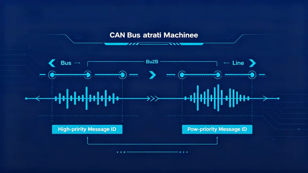
When multiple ECUs try to transmit at the same moment, a mechanism resolves the conflict. This is called CSMA/CD with arbitration. Each message carries an identifier. The message with the highest priority — the lowest numeric ID — automatically wins arbitration. It transmits without disruption. Lower-priority messages simply wait their turn.
Message Filtering
Every ECU on the network actually receives every message. But each one only processes the ones relevant to it. It filters based on that identifier.
Physical Topology
Physically, this runs on a linear bus topology. Each ECU connects to the main bus through short stubs. 120Ω resistors terminate both ends of the line. This prevents signal reflections that would otherwise corrupt the data.
Speed
On speed, high-speed CAN tops out at 1 Mbps. Typical automotive applications commonly run at 500 kbps or 250 kbps. This depends on what the specific system actually needs.
Automotive CAN Bus Function: Core Roles in Vehicle Systems
CAN Bus does not serve one function. It is the shared communication layer underneath nearly every electronic system in a modern vehicle. This is exactly why aftermarket compatibility gets complicated.
Powertrain Systems
Engine control (RPM, temperature, throttle) runs through CAN Bus. Transmission control and traction control also coordinate through CAN Bus. This lets the engine and transmission ECUs actually work together rather than independently.
Chassis Systems
ABS, electronic stability control, and steering angle sensors share safety-critical data across systems. They do this through the same network.
Body Electronics
Door and trunk status, window controls, climate control, and lighting all run through CAN Bus. This enables centralized control and status monitoring.
Infotainment and Driver Information
Navigation, audio, the instrument cluster, and smartphone integration all depend on CAN Bus. They need it specifically for vehicle speed, reverse gear signal, steering wheel controls, and climate display data.
Safety and Diagnostics
Airbag systems and OBD-II diagnostic communication both run through CAN Bus. This enables fault detection and diagnostic trouble code reading.
Why This Matters for B2B Buyers
For B2B buyers, the infotainment line is where this gets practical fast. An aftermarket head unit has to integrate properly with a vehicle’s CAN Bus network. It must retain any of those original functions after installation. It needs to do more than just play navigation and music.
CAN Bus Wiring Explanation: Physical Layer & Connection Basics
The Twisted Pair
CAN Bus runs on a twisted pair of wires — CAN_H and CAN_L. That twist is not cosmetic. It reduces electromagnetic interference. It meaningfully improves noise immunity compared to a straight parallel run.
Differential Signaling
The signaling itself is differential. The voltage difference between CAN_H and CAN_L is what actually represents the data. Because both wires pick up the same ambient noise, that common-mode noise gets rejected. It does not corrupt the signal.
Termination Resistors
Termination matters just as much. 120Ω resistors sit at each end of the bus. They specifically prevent signal reflections. Without proper termination, communication becomes unreliable or fails outright.
Topology Rules
Topology follows a specific rule. Every node connects to the main bus through short stubs. The bus itself needs to run as a single line rather than a star pattern. Proper termination depends on that linear structure.
Length and Speed Trade-Off
Length and speed trade off directly against each other. 1 Mbps works up to roughly 40 meters. 125 kbps can stretch to around 500 meters.
Common Wiring Errors
In practice, wiring errors are some of the most common causes of installation failures in this category. These include wrong polarity, missing termination, and incorrect stub connections. This is worth knowing before troubleshooting turns into guesswork.
Car CAN Bus System Basics: Nodes, Messages & Network Types
Nodes
Every device connected to a CAN Bus network counts as a node. This includes ECUs, sensors, actuators, and head units. Each one carries a unique ID. This lets it send and receive messages on the shared bus.
Message Structure
A CAN message, or frame, follows a specific structure. It includes a start of frame, an identifier that determines priority, data length, the actual data bytes, a CRC for error checking, and an acknowledgment.
Baud Rate
Baud rate — the transmission speed — must match across every node on a given bus. Common rates run 125 kbps, 250 kbps, 500 kbps, and 1 Mbps. A mismatch between nodes breaks communication entirely.
Network Types
Three network types cover most automotive applications.
High-speed CAN (ISO 11898-2) — runs up to 1 Mbps. Handles powertrain, chassis, and safety-critical systems where speed and reliability both matter.
Low-speed, fault-tolerant CAN (ISO 11898-3) — tops out at 125 kbps. Covers body electronics. Notably, it can keep operating even with one wire damaged. This matters for less safety-critical systems.
CAN FD (ISO 11898-1:2015) — pushes up to 8 Mbps in the data phase. Supports larger data payloads. It is increasingly common in modern vehicles as data demands grow.
CAN Bus Signal Protocol Guide: Data Frame Structure & Protocol Basics
Data Frame Structure
A standard CAN data frame follows a fixed structure:
- Start of frame (1 bit)
- Identifier (11 bits for a standard frame)
- Remote transmission request (1 bit)
- IDE (1 bit)
- Data length code (4 bits)
- Data (0 to 8 bytes)
- CRC (15 bits)
- Acknowledgment (1 bit)
- End of frame (7 bits)
Arbitration
Arbitration is what makes this work without collisions. When multiple nodes attempt to transmit at the same moment, the message with the lowest numeric identifier wins. Higher-priority messages get sent first without disruption to the network.
Message Filtering
Message filtering happens on the receiving end. Nodes filter incoming messages based on identifier. They process only what is actually relevant to them. This keeps individual node processing load manageable even on a busy network.
Broadcast Protocol
Worth understanding clearly: CAN is fundamentally a broadcast protocol. Every node receives every message on the bus. Filtering happens at the receiving node itself, in hardware or software. It does not happen at the network level.
Why Decoders Must Be Vehicle-Specific
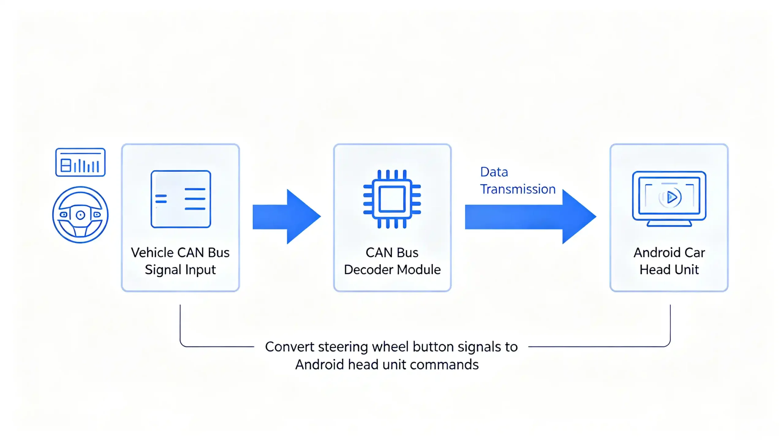
For B2B buyers, this is exactly why CAN Bus decoders have to be vehicle-specific. Different vehicles use different message formats and IDs. A decoder built for one brand’s protocol genuinely will not work correctly on another. It requires dedicated development.
Why CAN Bus Matters for B2B Automotive Electronics Procurement
Product Compatibility
Product compatibility comes down to this directly. Aftermarket head units must support the CAN Bus protocols of their target vehicle models. An incompatible decoder means losing steering wheel controls. It means losing the reverse camera trigger. It means losing climate display and other original functions the customer expects to keep working. For guidance on reverse camera integration, see our backup camera guide.
Impact on After-Sales Returns
CAN Bus mismatches are consistently among the top causes of after-sales returns and complaints in bulk orders. This makes supplier evaluation on this specific point worth real scrutiny.
What to Verify with Suppliers
Verify a supplier actually has in-house CAN Bus protocol development capability. Do not settle for a library of third-party decoders. In-house development adapts faster when a new vehicle model shows up.
Installation Considerations
Installation considerations matter too. Wiring errors like incorrect termination or wrong polarity lead directly to communication failures. Proper installation training and documentation genuinely reduce after-sales risk. They are not just a nice-to-have. For step-by-step installation guidance, see our head unit installation guide.
Practical Sourcing Advice
The practical sourcing advice: request a vehicle compatibility list from any supplier. Test samples on your actual target vehicles. Ask specifically about CAN Bus protocol development capability rather than assuming coverage. Suppliers with strong development capability support new vehicle models faster over time. This meaningfully reduces compatibility risk on every order that follows.
FAQ
How does CAN Bus differ from ordinary vehicle wiring?
Ordinary wiring connects components point to point. There is a dedicated wire for each signal. This is heavy, complex, and hard to scale as vehicles add more electronics. CAN Bus replaces much of that with a shared two-wire network. Multiple ECUs communicate over the same line. The system uses message priority rather than dedicated wiring to manage traffic. The result is a lighter, more flexible system that scales far better as vehicle electronics grow more complex.
Can an aftermarket head unit integrate with a vehicle’s CAN Bus?
Yes, but only through a CAN Bus decoder. The decoder translates the vehicle’s specific protocol into signals the aftermarket unit can interpret. Without a properly matched decoder, the head unit simply cannot read or respond to vehicle data. This includes steering wheel controls or the reverse camera trigger. Decoder quality and vehicle-specific matching are what actually determine how much original functionality survives the swap.
What happens if CAN Bus wiring is incorrect?
Incorrect wiring — reversed polarity, missing termination resistors, or improper stub connections — typically causes communication failures. These range from intermittent glitches to a complete loss of vehicle data functions. In some cases, it can also affect other systems sharing the same bus. This is why following documented wiring procedures during installation matters more than it might seem for a “simple” connection.
Why can’t an aftermarket head unit read CAN Bus signals directly?
Because aftermarket units are not natively built for any single vehicle’s specific CAN Bus protocol. A factory unit is. A decoder bridges that gap. It translates vehicle-specific message formats and IDs into something the aftermarket unit can understand. Without it, the unit might power on and play music fine. But it will not be able to read or respond to any of the vehicle’s own data.
Why does CAN Bus compatibility vary by vehicle?
CAN Bus protocols vary by vehicle brand. They often vary by model year as well. A product that works perfectly on one vehicle can fail to integrate properly on another. This happens without specific decoder development. For bulk orders, this makes vehicle-specific compatibility verification essential. Test samples on your actual target vehicles. Do not assume a supplier’s general compatibility claims cover your specific lineup.
Conclusion
CAN Bus is the communication layer that makes modern vehicle electronics work together. It also makes aftermarket products built to integrate with them actually work. Understanding its basic architecture, wiring, and protocol structure gives B2B buyers a real foundation. You can evaluate product compatibility and supplier capability. You no longer treat CAN Bus as a black box that either “works” or does not.